|
| Fig. 1 - Arduino with TEA5767 and LCD shield fully assembled |
Background
In my last post I described the Arduino libray I wrote for TEA5767 FM Radio module. In this post I´ll show a complete application that uses this library. The source code of this post can be found in GitHub in the library examples folder.
Note: This project does not claim to be production-ready. It's only a demonstration for a possible use of the library.
Scope
Because the main focus of this post is the software, the hardware will not be described in much detail here. Even so, I believe that anyone with some experience in electronics will be able to assemble this shield.
Description
This project deals with several software and hardware issues.
The software takes care of building a menu, respond to LCD Shield button events and control the radio module.
The hardware solves the problem of the TEA5767 audio output that has not enough current to drive earphones and its absent of volume control.
Modules
This radio application is composed of 3 modules: LCD Keypad shield, TEA5767 FM radio shield and Arduino Leonardo. The LCD and radio shields are controlled by Arduino.
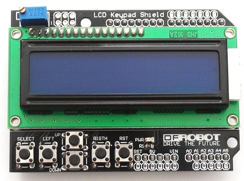
LCD Keypad Shield
 |
| Fig. 2 - LCD Keypad shield |
It contains 6 push buttons (one is connected directly to Arduino reset input) and one 16X2 Character LCD with backlight. And above all, this shield is economic about the Arduino pins it needs to operate: only 7 pins to interface with the LCD (4-bit mode), one pin to control backlight brightness and only one analog pin to interface with the 5 buttons.
A more detailed description can be found in the manufacturer site; the link is showed above.
 |
| Fig. 3 - Buttons connected to resistors as dividers so only one analog input is needed |
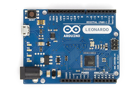
Arduino Leonardo
 |
| Fig. 4 - Arduino Leonardo |
I guess there's nothing new here. Besides this project was developed using Leonardo board, I believe it´s compatible with other versions as well.
Arduino pins used to interface with LCD and radio shields:
Pins SCL and SDA: communication with radio
Pins D4-D9: LCD control
Pin D10: Backlight brightness
Pins D11 and D12: Volume control
Pin A0: Input for the 5 buttons signals
FM Radio Module
 |
Fig. 5 - Radio shield with the TEA5767, the digital potentiometers, the
transistors amplifiers, the output jack and the pins for the LCD shield |
This is the Arduino shield I designed for the TEA5767 radio. In addition to the TEA5767 radio module, it has two digital potentiometers for volume control and a pair of unipolar transistors so this shield outputs can drive earphones.
The output can be connected to earphones or amplified speakers because the transistors only amplify current, not voltage (e.g. gain is ~1).
Besides the large number of pins that is seen in the board, only four of them are used by the circuit to exchange data with Arduino plus other two for power. The other pins are present to expose all the Arduino terminals to other shields you may want to stack over this one (e.g. LCD shield or any other that connects only to unused pins).
Schematics
Below is the circuit of the board seen in figure 5.
 |
| Fig. 6 - TEA5767 shield with digital potentiometer and current amplifier. |
TEA5767, as said many times here, is the FM radio module;
X9C103 is the digital potentiometer (10K ohm), responsible for the volume control. There are two of them, one for each audio channel. As can be seen in figure 6, they are connected to digital pins 11 and 12 of Arduino.
BC337 is a transistor configured as common collector and its function here is to amplify the TEA5767 current output so earphones can be used with the shield.
This schematic file can be found in this folder, under the examples folder. It was designed with P-CAD 2006 schematic editor.
Software
The software described here can be found on GitHub. It has a lot of comments to help the understanding, apart from the explanation that is seen in the next sections.
Application functions
The application functions are accessible via menus controlled by the key pad and are viewed in the LCD display.
Here is the menu structure:
Root
|- Mute
|- Search
|- Fine search
|- Register statn
|- Configuration
|- Search level
|- Low
|- Medium
|- High
|- Backlit inten.
|- Exit
|- Stand by
|- Load deflt stn
|- Exit
Each menu is accessed and each menu item is executed when you press the Select button in the key pad.
Below is the description of each menu item:
Note: some abbreviation was necessary due to LCD limits (2 rows x 16 columns)
Root: (Initial screen) It´s not actually a menu item, but what the program starts showing to the user and which contains the current selected station, Stereo/Mono status, Mute status and a bar graph for signal level. See figure 7.
At this state of the software, pressing the up and down buttons turn the volume up and down respectively. Also, pressing left and right buttons navigate through stations stored in memory.
 |
| Fig. 7 - Initial LCD screen view |
Mute: It's a toggle function. Pressing Select once, mutes the radio and pressing Select again turn the audio on. You can see the Mute status indication in figure 7.
Search: When pressed Select, shows the current station and let the user search for a station using the buttons Left and Right in the key pad. The audio is muted while searching to eliminate noise.
 |
| Fig. 8 - Mute and Search menu items |
Fine search: When pressed Select, shows a screen similar to which is viewed pressing Search menu option, but this search is more fine grained because is done 0.1 MHz at a time.
Register statn: (Register stations) When pressed Select over it, starts a scan that covers the whole FM band and register the found stations in an array in memory.
 |
| Fig. 9 - Fine search and Register stations menu items |
Configuration: Take the user to another menu, showing Search level and Backlight intensity menu items.
 |
| Fig. 10 - Configuration and Stand by menu items |
Search level: Take the user to another menu, showing High, Medium and Low menu items that are minimum levels required to select a station during a search.
Backlit inten.: (Backlight intensity) Using the Left and Right buttons it's possible to change the LCD backlight intensity.
Note: This function is here just for control demonstration as any intensity lower than maximum generates noise in audio due to PWM high frequency.
 |
| Fig. 11 - Search levela and Backlight intensity menu items |
Stand by: This option turns off the TEA5767 and the LCD backlight to save energy. It lowers the current from 155 to 65 mA. See figure 10.
Load deflt stn: (Load default station) Overrides the stations that may have been loaded by a previous search with the predefined ones.
Exit: Leaves current function and take the user to the Root screen.
 |
| Fig, 12 - Load default stations and Exit menu items |
Source code
Initializing the radio object
This is a simple task. After importing the library, call the TEA5767N constructor and stores the object in the radio global variable. This variable will be used through out the application code.
Initializing the LCD object
This code calls the LiquidCrystal constructor and stores the object in the lcd global variable. This variable will also be used through out the application code. The constructor parameters are the Arduino pins and are described in the comment of the code above.
Data Structure
Those are the constants used in the code and let it easier to read.
The button codes are arbitrary; they simply link a button in the LCD keypad to a value read from Arduino's analog pin A0, as seen in the code below:
Note: analogRead() is a function from Arduino library that reads the voltage present at one of the analog inputs (in this case, the input 0) and return a value between 0 and 1023 that corresponds to 0 to 5V (more on that here).
The menu constants define the dimension of the multidimensional array that contains the menu texts, as seen below:
And some other global variables are declared to support the program's execution flow. This will be explored in greater detail in the next sections.
System initialization
Every Arduino program has a setup() hook function that is called only once and is commonly used to initialize variables and pin modes among other things. And that's how it is used in this application as shown in the following code snippet.
The first three lines set the direction of the pins as output, i.e., the information flows from Arduino to its peripherals. It is necessary so the the next three commands may be issued correctly; they do the setup of volume and backlight intensity.
Next we have the LCD screen initialization. Those are calls to the LCD library.
The last two lines are calls to the radio library and are methods that help to reduce noise in the audio.
And we have the loadConfiguration() function that gathers several other specific configurations as we'll see next.
The first line in the method is a call to mute() on radio object so any noise caused by radio configuration is not noticed by the user.
Next we have the loadDefaultStations() that simply makes a copy of predefined stations into the stations array.
Then there is the loadStation() function that reads the station that was previously stored in the Arduino static (EEPROM) memory. Once read, uses the radio library to set it with the station value.
The loadSearchLevel() function also reads data from the Arduino static memory, this time to configure the minimum signal level required so a station can be found by a search.
The loadBacklightIntensity() function reads one byte from memory that corresponds to the backlight intensity that was previously stored.
The setupVolume() function is responsible for put the audio output to a level that is more pleasant to the user. First it lowers the volume to zero so both channels have the same level and then raises them to fifteen percent of the maximum. When we energize the system, the digital potentiometers may have different values, hence the need to lower them to zero.
And finaly, the sound is turned on again via a call to method turnTheSoundBackOn() on the radio library, now that all sources of noise during initialization are no longer present.
Execution
After the setup() function returns from execution, another hook function is called: loop(). And its name reveals exactly what it does, i.e., all code put inside of it is repeatedly executed; the execution gets trapped inside this function.
It starts reading the LCD keypad buttons and storing the value in a global variable.
Next there is a code that takes care of changing the state of the system from standby to active if any button is pressed. It reminds a lot what is done during system initialization because it´s returning from inactive state; it has to restore some variable states, set the radio station, restore LCD backlight and LCD information.
Lcd menu control code
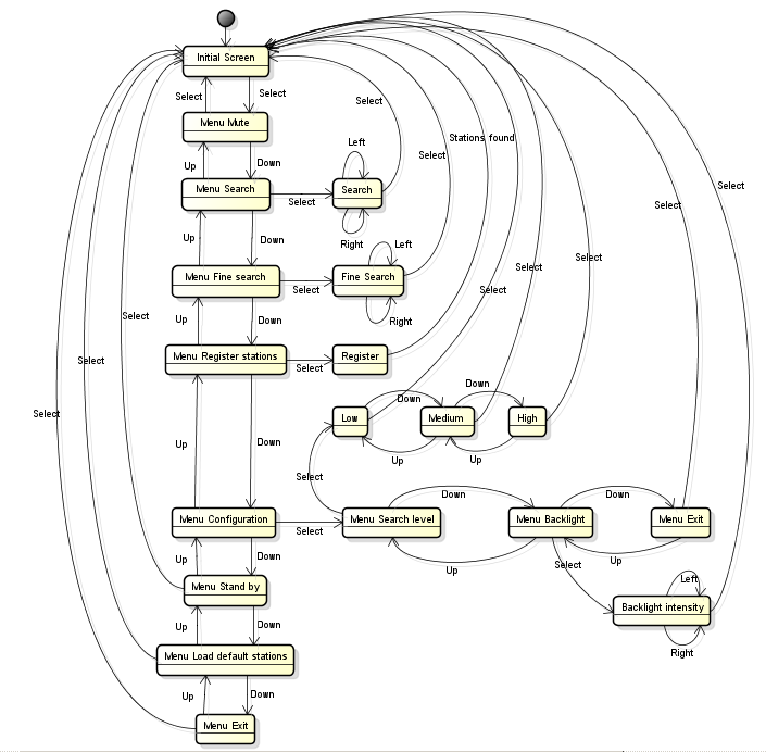 |
| Fig. 13 - Statechart showing possible menu states and possible events that may be applied via buttons |
The statechart above depicts the possible menu states defined by the application. Select, Up, Down, Left and Right are events that correspond to pressing the LCD module buttons.
This diagram was drawed with Astah and can be found in this folder.
The Select event that causes the change from a given state to the Initial (Root) screen, also execute some other codes. In the code, the states and events are managed by the switch / case structure. Those are described next.
Note: It's possible to load this application into Arduino and test it in conjunction with only the LCD key shield, without the radio shield. This may be helpful to turn this example into another type of application that requires a menu.
The outer switch command takes the LCD button code as a parameter and decide what other commands must be executed. Those commands lead to other inner switch commands that take the application state or the menu item selected and decide yet other commands to execute.
The application states may be understood as the states shown in the statechart in figure 13. A lcd button press generates almost all of the events in the statechart; the Stations found event happens automatically when all stations were found during the execution of Register event.
Let's now look at the switch code structure. As this is an extensive code, we'll dive into it little by little.
As said before, the outer switch() statement interprets the code of the button that was pressed while the user is seeing the main screen (fig. 7). The code guarded by btnNONE option is an exception, as it is not an event, but is executed if no button is pressed. As most of the time no button is pressed, this is a good place to put code that do regular maintenance and check, like using the radio library to check stereo status and update signal bar graph.
In the code above, updateLevelIndicator() just reads the signal level calling radio.getSignalLevel() and fill the second line of the LCD with an amount of characters that is proportional to the signal level read.
Back to the code outer_switch.cpp, we can see that before any command is accepted, the referred button must be in released state prior to the reading, i.e., no matter how long you keep the button pressed, the command will be executed only once; you must release the button and click again so that a new command is executed. An exception is made when applicationState = 0 (application is in initial state) and buttons Up or Down are pressed (for applicationState = 0, up and down buttons control the audio level), because is desirable that the audio level is continuously changed while the buttons are kept pressed.
So, what the volume up and down does is to pulse the digital potentiometer pins. For the other states, it's basically menu navigation.
Let´s see now how the Right button behave. The Left button has the same behavior, but backwards.
For application state = 0, Right button causes the increment of the stations array index and the load of the station selected to the radio via radio library methods. Finally, the LCD display is updated and the station is stored in memory.
For application state = 5, the Right button initiates a search upwards the current station. If band limit is found, tries to find a station downwards. Then, the LCD display is updated.
For application state = 6, each click in the button causes an increment of 100 kHz in the current station. Then the resulting station is loaded to the radio, the LCD display is updated and the station is stored in memory.
For application state = 7, each click in the button increases the LCD backlight intensity up to a maximum of 255. The result is stored in the static memory so the next time the system is turned on, it starts with the selected intensity.
And now the Select event.
From the statechart in the fig. 13 we can see that the Select event causes two types of change happen: change the state back to initial state or change the execution to another menu level.
If application state = 0, that is, the initial screen is being shown (fig. 7) , and the user hits the Select button, then the application state is changed to 1 and now the first two menu items are displayed and the current selected menu is Mute. Now the user can navigate to other menu items using Up and Down buttons or click Select again and, as current selected menu is Mute, the inner switch execute the radio mute() method which causes the application state change to 0 again and present the initial screen to the user. This is shown in the code snippet below.
I believe that with this brief explanation and the statechart, is possible to grasp the rest of the Select event execution. This way, we can see that, control of the execution of the application is a matter of control the application state and the selected menu item.
Conclusion
What took most of my time was the writing of this post, but I enjoyed a lot. Developing the application was very important to test and find the flaws in the library and if it was easy to use.
The application requires a lot of memory (~17K bytes), but still far from the ~28K bytes that is available in Arduino. This leaves room for a lot of improvements and one I can think now is that all the search could happen before send the command to the radio; this would save a lot of time for the user that knows exactly what station he / she wants to hear.
The TEA5767 library that was used in this application is not limited to this hardware. It's possible to use another Arduino hardware and another HMI (Human Machine Interface) like Nokia 5110 LCD or even a smartphone running Android. By the way, controlling this radio remotely via an Android App is the subject of my next post.
Thank You
Please let me know if this post somehow helped you in your projects.
To follow my updates to this library and my other projects: